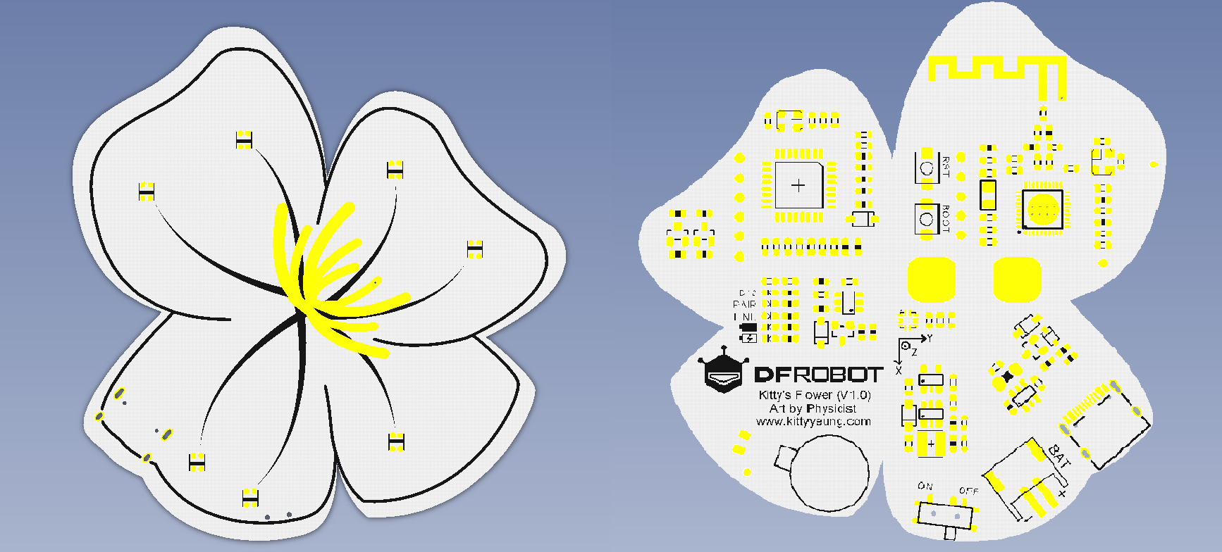
Premessa: Kitty’s Flower è una coppia di spille indossabili Bluetooth.Create congiuntamente da Art by Physicist e DFRobot, sono appositamente progettate per scenari applicativi indossabili, sistema integrato di gestione dell’alimentazione, luci LED RGB, accelerometro, sensori, vibrazioni e touch.Supporta Arduino e Scratch programmazione e può essere utilizzata come unità di controllo intelligente di base per prodotti indossabili, installazioni di arte interattiva e nuovi accessori.Due sono abbinati in coppia e vari effetti possono essere programmati dagli utenti.Le funzioni impostate in fabbrica sono programmate per quanto sopra scenario menzionato.Le spille da compagnia si abbinano all’abito Flower (top, pantaloncini e coprimaschera) con pittura digitale a mano su tessuto e fiori stampati in 3D su tulle.

CARATTERISTICHE TECNICHE:
- Microcontrollore: ATmega328
- Tipo di chip BLE: TI CC2540
- Supporta Bluetooth HID
- Debug del modulo Bluetooth tramite il comando AT
- Comunicazione della porta seriale
- Aggiornamento firmware USB BLELE
- Interfaccia di alimentazione: batteria al litio USB/3.7V, connettore JST
- Gamma di alimentazione esterna: 7-12V
- Bootloader: Arduino UNO
- Dimensioni: 70mm*70mm
- Peso: 30 g
LISTA MATERIALI:
-
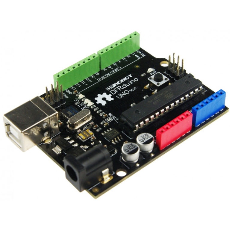 DFRduino UNO V2.1€19.00
 -
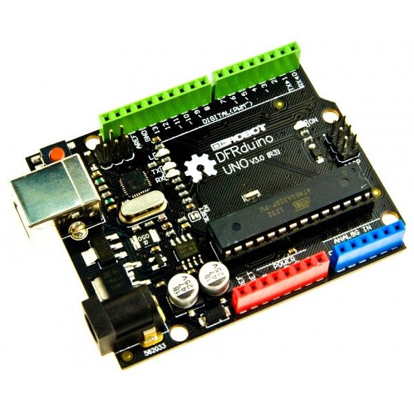 DFRduino UNO R3€18.50
PANORAMICA DELLA SCHEDA:
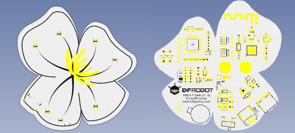
1 Motore a vibrazione D5
2 Tocco D6
3 LED RGB D9
4 Accelerometro a 3 assi LIS2DH I2C
Kitty Flower integra più funzioni, le mostreremo una per una di seguito, ma nell’uso effettivo, aggiorna Kitty Flowers Demo separatamente: KittyMother e KittyChild due demo per completare l’accoppiamento e la connessione.Le due demo imposteranno automaticamente lo stato master/slave delle schede madri, quindi leggere il valore dell’intensità del campo RSSI Bluetooth per determinare la distanza tra loro.
CODICE DI ESEMPIO PER MOTORE A VIBRAZIONE:
#define VMPIN      5     //Vibration motor pin

void setup() {
  // initialize digital pin LED_BUILTIN as an output.
  pinMode(VMPIN, OUTPUT);
}

// the loop function runs over and over again forever
void loop() {
  digitalWrite(VMPIN, HIGH);   // turn the Motor on (HIGH is the voltage level)
  delay(1000);                       // wait for a second
  digitalWrite(VMPIN, LOW);    // turn the Motor off by making the voltage LOW
  delay(1000);                       // wait for a second
}
CODICE DI ESEMPIO PER TOUCH:
#define TOUCHPIN   6

void setup() {
  // initialize serial communication at 9600 bits per second:
  Serial.begin(115200);
  // make the pushbutton's pin an input:
  pinMode(TOUCHPIN, INPUT);
}

// the loop routine runs over and over again forever:
void loop() {
  // read the input pin:
  int touchState = digitalRead(TOUCHPIN);
  // print out the state of the button:
  Serial.println(touchState);
  delay(10);        // delay in between reads for stability
}
Apri la porta seriale, tocca lo stame, la porta seriale emetterà un livello alto; altrimenti, emetterà un livello basso
CODICE DI ESEMPIO PER LED RGB:
librerie:
Adafruit_NeoPixel LGPL-3.0: github.com/adafruit/Adafruit_NeoPixel
  #include <Adafruit_NeoPixel.h>

    #define PIN 9     //The signal pin connected with Arduino
    #define LED_COUNT 60 // the amount of the leds of your strip

    // Create an instance of the Adafruit_NeoPixel class called "leds".
    // That'll be what we refer to from here on...
    Adafruit_NeoPixel leds = Adafruit_NeoPixel(LED_COUNT, PIN, NEO_GRB + NEO_KHZ800);

    void setup()
    {
      leds.begin();  // Call this to start up the LED strip.
      clearLEDs();   // This function, defined below, turns all LEDs off...
      leds.show();   // ...but the LEDs don't actually update until you call this.
    }

    void loop()
    {
        for (int i=0; i<LED_COUNT; i++)
      {
        rainbow(i);
        delay(10);  // Delay between rainbow slides
      }
    }


    // Sets all LEDs to off, but DOES NOT update the display;
    // call leds.show() to actually turn them off after this.
    void clearLEDs()
    {
      for (int i=0; i<LED_COUNT; i++)
      {
        leds.setPixelColor(i, 0);
      }
    }

    // Prints a rainbow on the ENTIRE LED strip.
    //  The rainbow begins at a specified position.
    // ROY G BIV!
    void rainbow(byte startPosition)
    {
      // Need to scale our rainbow. We want a variety of colors, even if there
      // are just 10 or so pixels.
      int rainbowScale = 192 / LED_COUNT;

      // Next we setup each pixel with the right color
      for (int i=0; i<LED_COUNT; i++)
      {
        // There are 192 total colors we can get out of the rainbowOrder function.
        // It'll return a color between red->orange->green->...->violet for 0-191.
        leds.setPixelColor(i, rainbowOrder((rainbowScale * (i + startPosition)) % 192));
      }
      // Finally, actually turn the LEDs on:
      leds.show();
    }

    // Input a value 0 to 191 to get a color value.
    // The colors are a transition red->yellow->green->aqua->blue->fuchsia->red...
    //  Adapted from Wheel function in the Adafruit_NeoPixel library example sketch
    uint32_t rainbowOrder(byte position)
    {
      // 6 total zones of color change:
      if (position < 31)  // Red -> Yellow (Red = FF, blue = 0, green goes 00-FF)
      {
        return leds.Color(0xFF, position * 8, 0);
      }
      else if (position < 63)  // Yellow -> Green (Green = FF, blue = 0, red goes FF->00)
      {
        position -= 31;
        return leds.Color(0xFF - position * 8, 0xFF, 0);
      }
      else if (position < 95)  // Green->Aqua (Green = FF, red = 0, blue goes 00->FF)
      {
        position -= 63;
        return leds.Color(0, 0xFF, position * 8);
      }
      else if (position < 127)  // Aqua->Blue (Blue = FF, red = 0, green goes FF->00)
      {
        position -= 95;
        return leds.Color(0, 0xFF - position * 8, 0xFF);
      }
      else if (position < 159)  // Blue->Fuchsia (Blue = FF, green = 0, red goes 00->FF)
      {
        position -= 127;
        return leds.Color(position * 8, 0, 0xFF);
      }
      else  //160 <position< 191   Fuchsia->Red (Red = FF, green = 0, blue goes FF->00)
      {
        position -= 159;
        return leds.Color(0xFF, 0x00, 0xFF - position * 8);
      }
    }
CODICE DI ESEMPIO PER ACCELLEROMETRO:
librerie:
- Wire LGPL: arduino.cc/en/Reference/Wire
- DFRobot_LIS2DH12 LGPL: github.com/DFRobot/DFRobot_LIS2DH12
#include <Wire.h>
#include <DFRobot_LIS2DH12.h>

DFRobot_LIS2DH12 LIS; //Accelerometer

void setup() {
  Wire.begin();
  Serial.begin(115200);
  while (!Serial);
  delay(100);

  // Set measurement range
  // Ga: LIS2DH12_RANGE_2GA
  // Ga: LIS2DH12_RANGE_4GA
  // Ga: LIS2DH12_RANGE_8GA
  // Ga: LIS2DH12_RANGE_16GA
  while (LIS.init(LIS2DH12_RANGE_16GA) == -1) { //Equipment connection exception or I2C address error
    Serial.println("No I2C devices found");
    delay(1000);
  }
}

void loop() {
  acceleration();
}

/*!
    @brief Print the position result.
*/
void acceleration(void)
{
  int16_t x, y, z;

  delay(100);
  LIS.readXYZ(x, y, z);
  LIS.mgScale(x, y, z);
  Serial.print("Acceleration x: "); //print acceleration
  Serial.print(x);
  Serial.print(" mg \ty: ");
  Serial.print(y);
  Serial.print(" mg \tz: ");
  Serial.print(z);
  Serial.println(" mg");
}
Buon progetto.